Three distinct approaches to the same task — which one should you choose, when, and why? Fundamental principles, applications, and a comparative overview.
Riveting is the process of permanently joining two or more parts by controllably deforming a rivet element. Compared to welding or adhesive bonding, it requires no thermal input, can hold dissimilar materials together, and delivers repeatable strength values — which is why it remains indispensable in aerospace, automotive, and electronics.
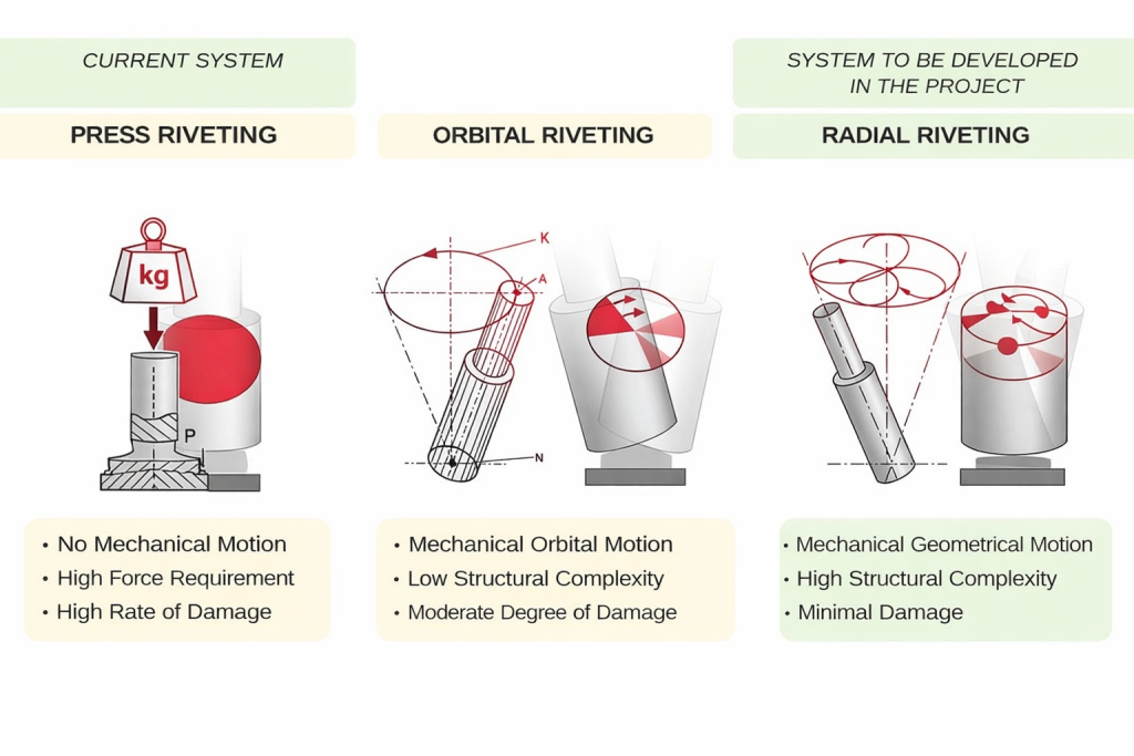
Yet “riveting” does not refer to a single technique. Depending on how the force is applied, how the tool moves geometrically, and how material flow is managed, three fundamentally different approaches emerge: press riveting, orbital riveting, and radial riveting. In this article, we examine each method through its working principle, typical applications, and comparative advantages and limitations.
1. Press Riveting (Impact / Squeeze Riveting)
Working Principle
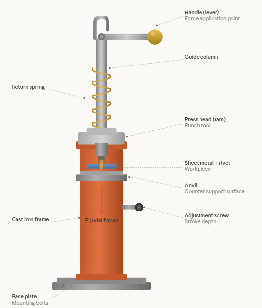
Press riveting is the most conventional method, in which a high axial compressive force is applied to the rivet element in a single stroke or a series of impacts. The tool contacts the entire rivet body simultaneously and forces the material into the desired shape in one pass. During this process, the free end of the rivet — known as the closing head or driven head — flares outward, clamping the sheets together to form a permanent joint.
In the experimental work by Markiewicz et al., this type of riveting process was shown to be divisible into seven distinct stages. In the initial stage, the rivet body is compressed and only the rivet material exceeds its yield stress. In subsequent stages, the rivet body expands until it contacts the edges of the punched hole, the closing head begins to form, and a material “lug” develops between the sheets due to friction. In the final stage, elastic springback occurs and the joint reaches equilibrium. Their study revealed strain values exceeding 20% in the riveting zone.
Witek’s finite element analyses on blind rivets paint a similar picture: upon completion of riveting, Von Mises residual stresses ranging from 164 to 329 MPa were measured in the rivet body. This initial stress field directly affects both the static and fatigue strength of the joint.
Applications
Press riveting has been widely used for decades in steel construction, shipbuilding, and traditional aircraft fuselage assembly. As noted in the review by Papuga and Stejskal, cold riveting — particularly with solid rivets — remains heavily employed in the aerospace industry, where parameters such as squeeze force, hole preparation, and surface treatment are among the critical variables determining the final fatigue life.
Advantages and Limitations
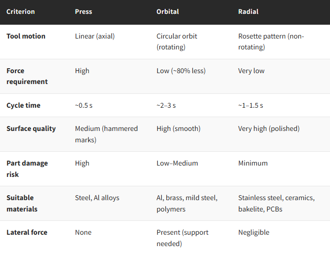
The most pronounced advantage of press riveting is its speed: a typical cycle time is around 0.5 seconds. In large-scale production, this speed difference significantly reduces total assembly time. Furthermore, press riveting with solid rivets creates a strong tangential compressive residual stress field around the hole — as the rivet body fully fills the hole — which delays crack initiation and extends fatigue life.
On the other hand, the high axial force requirement is the most significant drawback. When Papuga and Stejskal compared solid rivets with blind rivets, they found that blind rivets fail to adequately fill the hole and therefore cannot generate a meaningful residual stress field around it — which limits blind rivets to less structurally loaded joints. The high force also introduces a risk of damage to brittle or thin-walled components. In the experiments by Markiewicz et al., a severe strain gradient was observed in the sheets near the riveting zone, and it was demonstrated that when the edge margin falls below the nominal value recommended by calculation rules, the strain distribution becomes unbalanced and can lead to material embrittlement.
2. Orbital Riveting
Working Principle
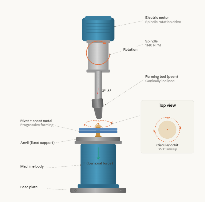
Orbital riveting is based on a conically inclined forming tool (typically at 3° or 6°) that rotates and traces a circular orbit over the rivet, progressively deforming the material in stages. The tool contacts only a small area of the rivet surface at any given moment; with each revolution, it moves only a fraction of the material. This “kneading” motion reduces the total axial force requirement by approximately 80% compared to press riveting.
While the tool is held at a fixed angle, the motor spindle rotates and creates a sweeping line of pressure spanning 360 degrees around the rivet axis. During this process, material flows outward from the centre; however, material near the rivet’s perimeter moves faster and farther than material near the centre. The resulting closing head possesses a smooth, symmetrical surface finish.
Applications
Thanks to its low force requirement, orbital riveting has found wide application in temperature-sensitive assemblies (polymers, tempered aluminium alloys), electronic component joining, and medical device manufacturing. The fact that the cold-forming process produces no heat, sparks, or contaminants enhances its suitability for cleanroom conditions. Moreover, its short cycle times in medium-to-high-volume production (under 3 seconds for small rivets) facilitate automation integration.
Aluminium alloys and mild steels (in the HRB 50–100 range) are the most suitable material group for orbital riveting. In semi-brittle materials such as magnesium, the progressive forming reduces the risk of cracking. However, the method’s effectiveness diminishes with hardened steels above HRC 32.
Advantages and Limitations
The most notable advantage of orbital riveting is its ability to produce high-quality joints with low force. The cold-forming process work-hardens the rivet material by 10–15%, which positively affects fatigue life. The closing head surface can be obtained virtually free of tool marks and near mirror quality (Ra < 1.0 µm) — a significant advantage in consumer products and optical mounts where cosmetic appearance matters.
On the other hand, control of material flow in orbital riveting is limited. A constant lateral force is present during forming, which means the workpiece requires firm support. The crescent-shaped contact area between the rotating tool and the rivet surface creates some surface friction. Furthermore, the method cannot be applied to blind rivets, as access to both sides of the assembly is required.
3. Radial Riveting
Working Principle
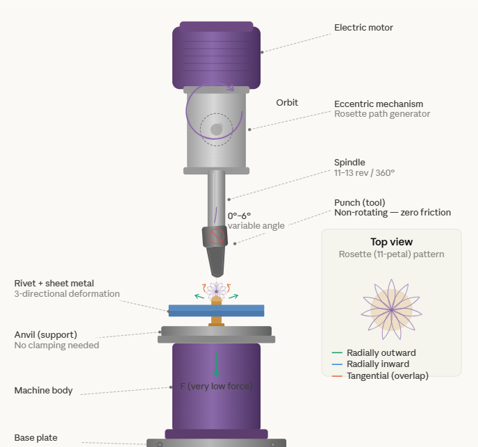
Radial riveting shares similarities with orbital riveting but contains fundamental differences in tool path and material flow. In radial riveting, the tool (punch) axis angle is not held fixed — it varies continuously between 0° and 6°. The tool traces an 11-petal rosette pattern over the rivet — much like the hypocycloid curve created by a Spirograph toy. Each petal of this pattern passes through the centre of the rivet.
The critical difference is this: in radial riveting, the tool itself does not rotate; it only follows the orbital path. This minimises friction between the tool and the workpiece to the absolute minimum, resulting in a flawless surface finish. The material deforms simultaneously in three directions — radially outward, radially inward, and tangentially overlapping. While one full revolution of the motor produces 360° of tool rotation in orbital riveting, radial riveting requires 11 to 13 motor revolutions to complete 360° of tool travel. This results in more gradual and more uniform material forming.
Applications
Radial riveting delivers its best performance on small-diameter, precision parts — consistent with the method’s original purpose. It was first developed in Europe in the 1960s for assembling tiny rivets in watch mechanisms. Today, its primary applications include joining on printed circuit boards (PCBs), electrical contacts, assemblies involving brittle materials such as ceramics or bakelite, high-torque D-profile shaft applications, and riveting hard materials like stainless steel (HRC 38 and above).
The fact that radial riveting produces virtually no lateral force eliminates the need for complex clamping fixtures, enabling assembly without them. This characteristic provides a significant advantage when working on fragile substrates.
Advantages and Limitations
The most distinctive advantage of radial riveting is that it distorts the molecular structure of the metal less than other methods. Material is moved at a constant speed and at a uniform rate, which translates to higher joint strength and improved electrical conductivity. Because the method is reported to enhance the conductivity of metal parts, it is frequently chosen for forming rivets that serve as electrical contacts.
On the other hand, the radial motion generation mechanism is more complex, and this is sometimes considered a disadvantage. Additionally, radial riveting is not recommended for tubular rivets or tube-like parts, because the material flow first moves toward the centre and then outward, which carries the risk of distorting the tube geometry. For such applications, orbital riveting provides a safer alternative.
Which Method, When?
None of these three methods renders the others obsolete; each one responds to different engineering requirements. Press riveting remains the primary choice in large-scale structural applications demanding high strength and speed — for instance, in aircraft fuselage panel assembly. As the comprehensive review by Papuga and Stejskal demonstrates, the residual stress field created by press riveting with solid rivets is superior to other methods in its capacity to delay crack initiation.
Orbital riveting comes to the forefront in medium-to-high-volume production where low-force operation is mandatory, where parts are temperature-sensitive, or where cosmetic appearance matters. The cleanroom compatibility offered by the cold-forming process makes it indispensable in the medical and electronics sectors.
Radial riveting is undeniably the best option in applications where precision, minimum part damage, and electrical conductivity are critical — particularly for small-diameter rivets, fragile substrates, and PCB assemblies.
The right method selection depends on a holistic evaluation of parameters such as the type and hardness of the materials being joined, the rivet diameter, the desired joint strength, surface quality expectations, cycle time targets, and production volume. Engineering, as always, is about finding not “the best” but “the most suitable.”
References
[1] Papuga, J. & Stejskal, J. (2022). Effect of some riveting process parameters on the fatigue life of double-shear lap joints. Engineering Failure Analysis, 134, 106008.
[2] Markiewicz, E., Langrand, B., Deletombe, E., Drazetic, P. & Patronelli, L. (1998). Analysis of the riveting process forming mechanisms. Int. J. of Materials and Product Technology, 13(3–6), 123–145.
[3] Witek, L. (2006). Numerical simulation of riveting process using blind rivet. Aviation, X(2), 7–12.
[4] Wenghöfer, F. Riveting — Course: Technique for Manual Working of Materials. Methodical Guide for Instructors. IBE, Berlin.